Hydrologic Model Representation of LID Controls
A LID control (see LID Control Types’) is modeled as a combination of vertical layers. The specific combination of layers present depends on the type of LID control, but in general they are:
- Surface Layer (may include vegetation)
- Soil Layer or Pavement Layer
- Storage Layer (typically gravel)
- Underdrain Piping
The model performs a moisture balance that tracks how much water moves between the layers and how much is stored within each layer. The figure below illustrates the processes considered for a bioretention cell or porous block pavement system.

The physical and performance characteristics of LID controls are defined in the Low Impact Development Controls Manager’ on a per-unit-area basis. Thus, the same LID control design can easily be used in multiple locations in the network, over differently sized areas.
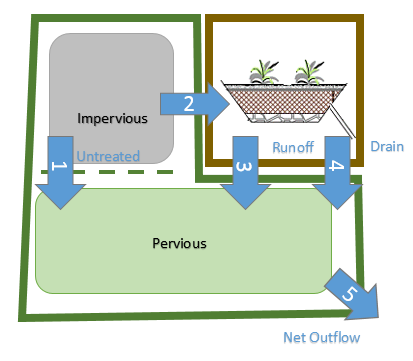
The interaction between Parent Catchment area and LID Control area can be summarized with the following figure: